
What it controls
Straightness answers one simple question: “How much may this line wander?” It can control a surface line or the axis of a feature of size. A line on a surface, or the derived axis of a feature such as a shaft.
The tolerance zone
How the zone works
For a surface element, picture two straight, parallel lines separated by the tolerance. The controlled line element must remain between them. When straightness controls an axis of a feature of size, the zone is normally a cylinder, so the frame includes a diameter symbol.
Example drawings
See Straightness on a drawing
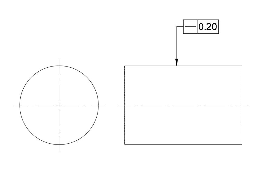
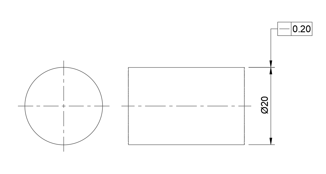
Tolerance zone visualized
See the tolerance zone in context
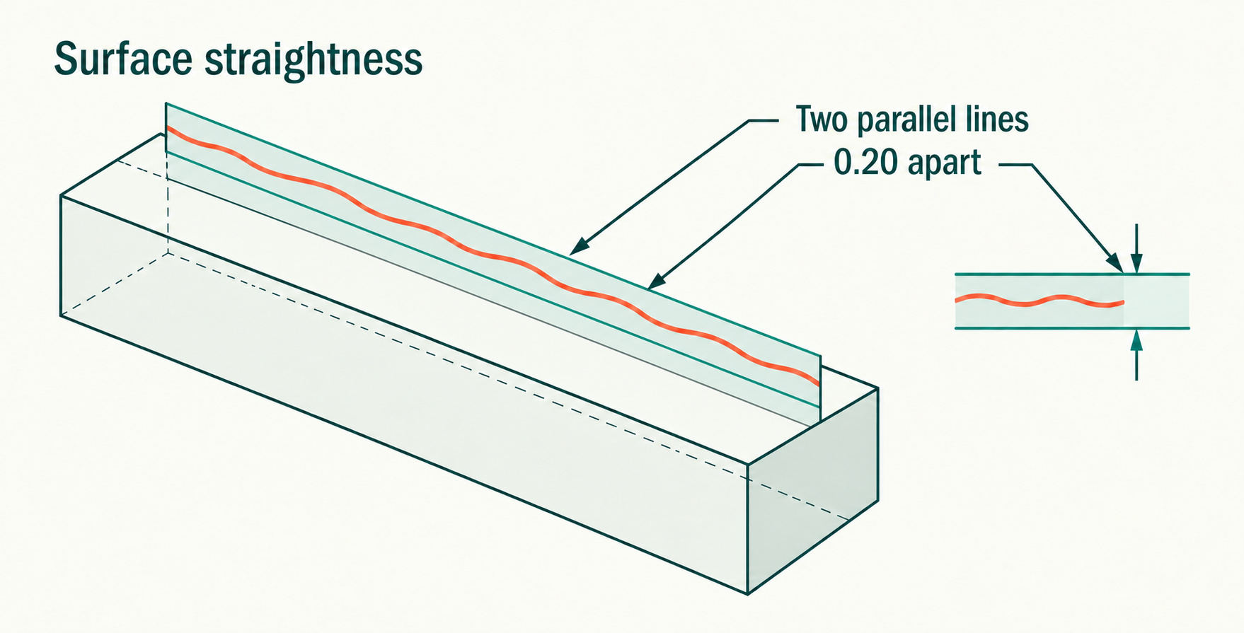
Surface straightness vs. axis straightness
The leader location changes the meaning. A callout aimed at a surface controls each specified line element on that surface. A callout associated with a shaft or hole size controls the derived axis instead. An axis can be straight even when individual surface lines have finish or waviness, and the reverse can also be true.
Example feature control frame
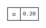
The indicated surface line must remain between two parallel lines 0.20 mm apart.
Practical use
When to use Straightness
Use surface straightness for a rail, guide, or sealing edge that needs a clean straight path. Use axis straightness when a long pin, shaft, or bore must avoid bending while still allowing its location to float.
Inspection
How it is usually measured
Inspect a surface line with an indicator, height gage, optical method, or CMM along the specified direction. For an axis, a CMM or a suitable functional gage evaluates the derived axis. The setup should match the feature and the drawing requirement—not a convenient unrelated surface.
Common mix-up
A straightness control on a surface and one on an axis are not the same. Check what the leader touches.
Keep exploring
 Flatness
 Circularity
 Cylindricity
 Profile of a Line
 Profile of a Surface
 Angularity
 Perpendicularity
 Parallelism
 Position
 Circular Runout
 Total Runout
 Concentricity
 Symmetry