
What it controls
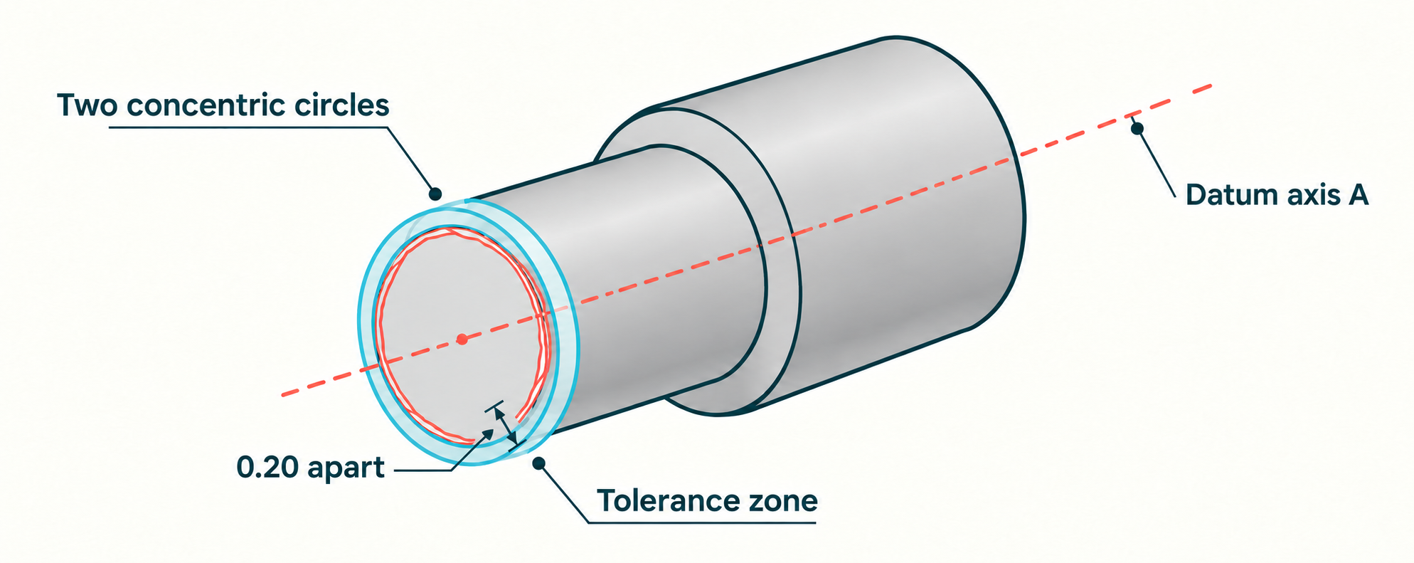
Circular runout is measured while the part rotates about a datum axis. At each circular cross-section, the indicator variation may not exceed the tolerance. Individual circular elements of a surface relative to a datum axis.
The tolerance zone
How the zone works
With the part rotated about its datum axis, the indicator variation at any one circular cross-section must not exceed the stated tolerance. Each cross-section is evaluated separately.
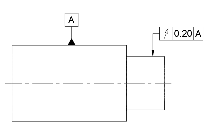
Example drawing
See Circular Runout on a drawing
Tolerance zone visualized
See the tolerance zone in context
Rotation reveals several errors at once
Circular runout relates the actual surface to a datum axis while the part turns. At a given section, it can reflect effects of circularity, coaxiality, and local surface variation. It does not control the full surface from end to end—that is total runout.
Example feature control frame
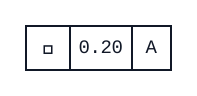
At any cross-section of the indicated diameter, indicator variation during rotation about datum A must not exceed 0.20 mm.
Practical use
When to use Circular Runout
Use it for a rotating diameter, flange face, or short functional band where low variation at each measured slice matters, but a full-length sweep is unnecessary.
Inspection
How it is usually measured
Support or locate the part from the datum feature so the part rotates about the datum axis, then place an indicator on the controlled surface and rotate it one revolution. Repeat at the required cross-sections. The setup is everything: rotating from an arbitrary diameter instead of the datum feature changes the result.
Common mix-up
It checks one circular slice at a time, so it does not fully control the surface along its length.
Keep exploring
 Straightness
 Flatness
 Circularity
 Cylindricity
 Profile of a Line
 Profile of a Surface
 Angularity
 Perpendicularity
 Parallelism
 Position
 Total Runout
 Concentricity
 Symmetry