What it controls
Profile of a line wraps a two-dimensional tolerance band around the true profile at every specified cross-section. It is useful for curves that cannot be described by basic radii alone. The line elements in the drawing view or cross-sections identified by the callout.
The tolerance zone
How the zone works
The tolerance zone is bounded by two offset curves around the true profile in the specified drawing view or cross-section. Unless another condition is stated, the band is equally disposed on both sides of the true profile.
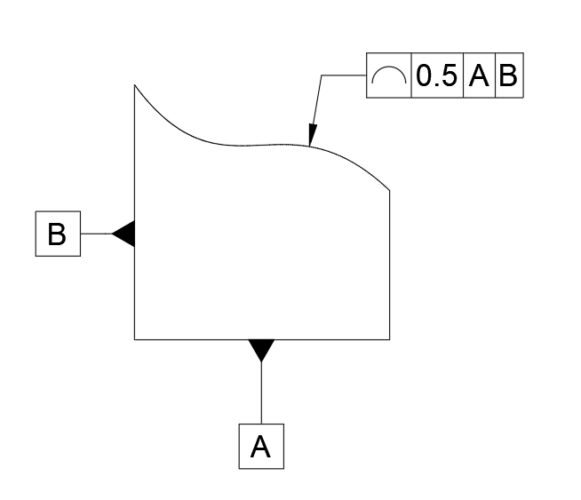
Example drawing
See Profile of a Line on a drawing
Tolerance zone visualized
See the tolerance zone in context
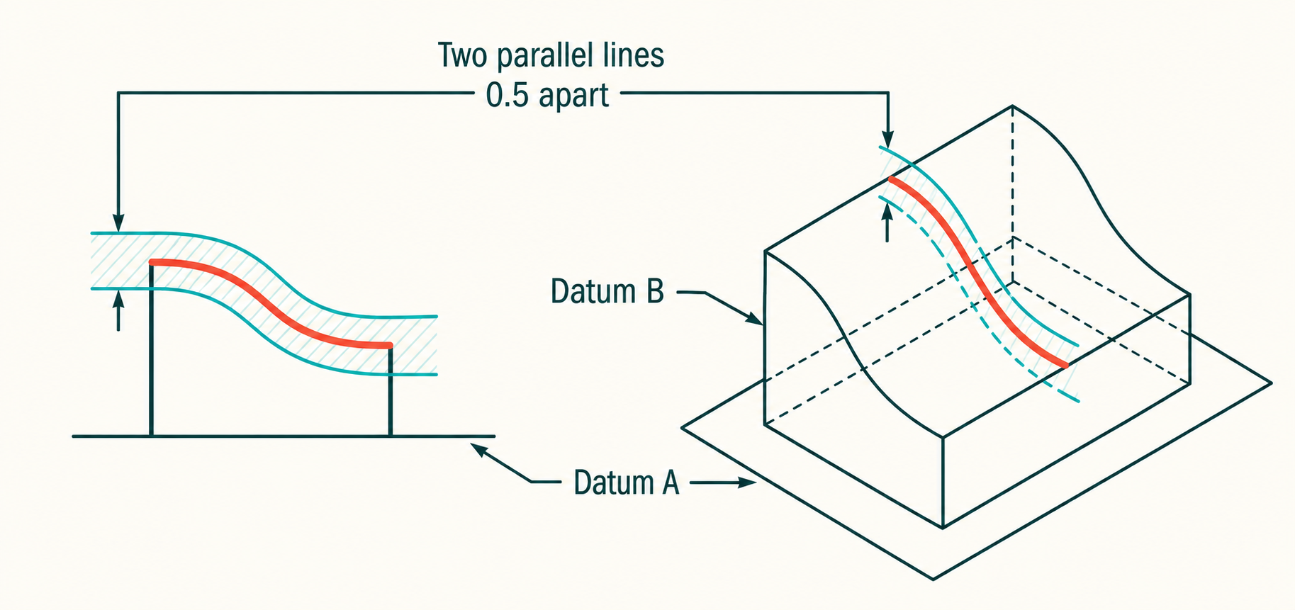
A profile control for one section at a time
Profile of a line applies to line elements, not the whole 3D skin. The drawing should make clear which views, sections, or cross-sections are controlled. When datums appear in the frame, they orient and locate the true profile; without datums, the control acts as a form refinement only.
Example feature control frame
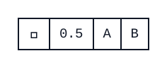
Each indicated airfoil cross-section must lie within a 0.5 mm wide profile zone located from datums A and B.
Practical use
When to use Profile of a Line
Use it for a cam-like contour, airfoil section, formed cross-section, or a curve where a radius-plus-size tolerance would not communicate the functional shape well.
Inspection
How it is usually measured
Establish any datum references first, then compare measured points in the specified 2D section against the basic profile. A CMM, optical comparator, scan, or dedicated section gage may be appropriate. Record the section being evaluated; a good result in one slice does not prove the entire surface is acceptable.
Common mix-up
Be explicit about the cross-sections being controlled; profile of a surface is the 3D alternative.
Keep exploring
 Straightness
 Flatness
 Circularity
 Cylindricity
 Profile of a Surface
 Angularity
 Perpendicularity
 Parallelism
 Position
 Circular Runout
 Total Runout
 Concentricity
 Symmetry