
What it controls
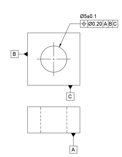
Position is the most widely used GD&T control for holes, pins, and slots. It defines a zone around the true location where the feature’s axis or center plane must remain. The axis or center plane of a feature of size.
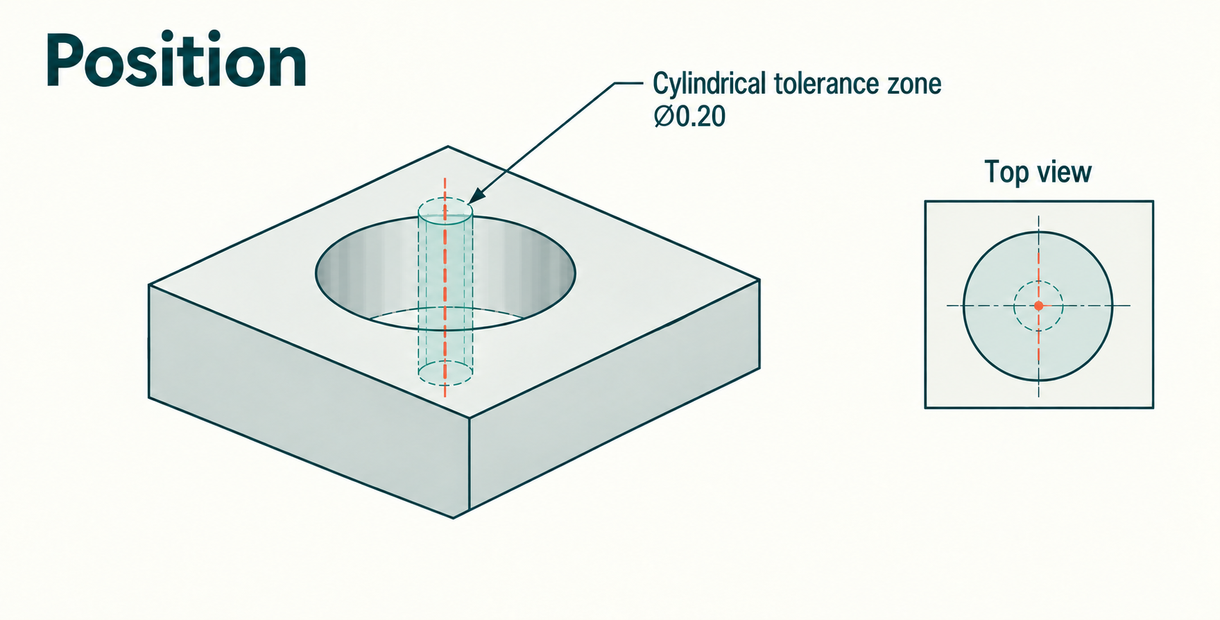
The tolerance zone
How the zone works
For a round hole or pin, position commonly creates a cylindrical zone centered on the true position. The actual axis must remain inside it. For slots and tabs, the zone can be two parallel planes applied to the derived center plane.
Example drawing
See Position on a drawing
Tolerance zone visualized
See the tolerance zone in context
Location, orientation, and possible bonus tolerance
Basic dimensions define the exact target location; the position tolerance defines the allowed zone around that target. The datum reference frame orients and locates the zone. A material-condition modifier such as MMC may allow bonus tolerance as a hole becomes larger or a pin becomes smaller, while protecting assembly at the virtual condition.
Example feature control frame
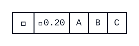
The indicated hole axis must lie within a ⌀0.20 mm zone located from datums A, B, and C.
Practical use
When to use Position
Use position for hole patterns, locating pins, slots, fastener features, and other features of size whose ability to assemble matters more than separate X, Y, and angle tolerances.
Inspection
How it is usually measured
Set up the part to its primary, secondary, and tertiary datums in the order shown. A CMM can report the feature axis versus the true-position zone; for repeating production checks, a functional gage can often verify the virtual condition much faster. Be sure the basic dimensions, material modifier, and datum modifiers are part of the inspection plan.
Common mix-up
Position works with basic dimensions. The dimensions locating the true position should be boxed, not given ± tolerances.
Keep exploring
 Straightness
 Flatness
 Circularity
 Cylindricity
 Profile of a Line
 Profile of a Surface
 Angularity
 Perpendicularity
 Parallelism
 Circular Runout
 Total Runout
 Concentricity
 Symmetry