What it controls
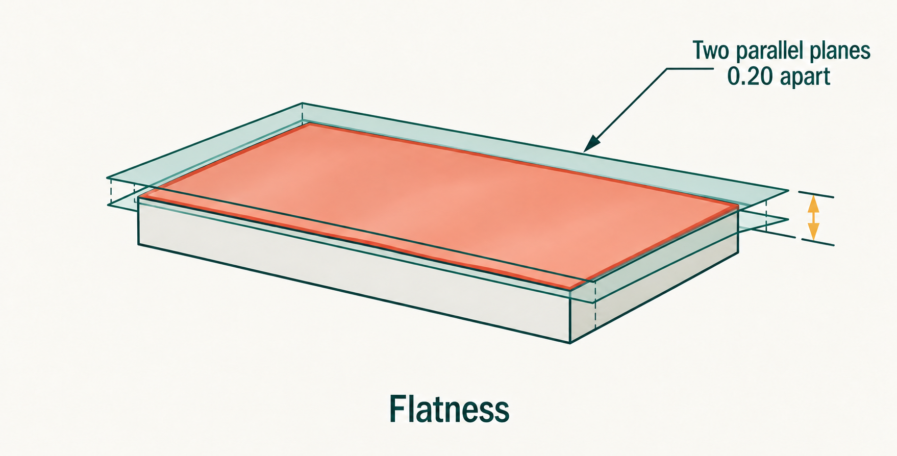
Flatness controls the shape of one surface without referencing anything else. Imagine two perfectly flat glass plates separated by the tolerance value: the surface must fit between them. The full surface called out by the leader.
The tolerance zone
How the zone works
Flatness creates two perfectly parallel planes separated by the stated value. Every point of the controlled surface must fit inside that space. The zone is free to tip and shift; it is not anchored to a datum or a granite table.
Example drawings
See Flatness on a drawing
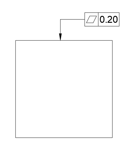
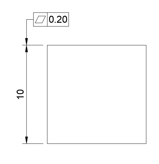
Tolerance zone visualized
See the tolerance zone in context
Surface flatness vs. feature-of-size flatness
The usual application is surface flatness: the feature control frame points directly to one planar face, such as a mounting or sealing face. Flatness can also be applied to a feature of size—the space between two opposed parallel faces. In that less common case it controls the derived median plane, an imaginary plane built halfway between the opposed surface elements. It does not mean each face is individually flat, and it does not make the two faces coplanar with any other surface.
Example feature control frame
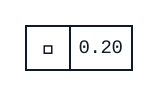
The indicated mounting face must fit between two parallel planes 0.20 mm apart.
Practical use
When to use Flatness
Choose flatness when a face needs to seat evenly, seal, resist rocking, or create a dependable datum feature. It is often more functional than tightening every local size dimension because it controls the whole surface as one requirement.
Inspection
How it is usually measured
A CMM can sample the surface and calculate the minimum separation of two parallel planes that encloses it. On the shop floor, use a stable three-point support or another method that lets the part settle independently, then sweep the surface with an indicator or height gage. Simply resting the part on the face being checked and measuring from the table can accidentally evaluate parallelism instead of true flatness. Derived-median-plane flatness is commonly checked with a CMM or a functional setup designed for the size condition.
Common mix-up
Flatness does not tell you whether the surface is level relative to another feature. For that, use an orientation control such as parallelism.
Keep exploring
 Straightness
 Circularity
 Cylindricity
 Profile of a Line
 Profile of a Surface
 Angularity
 Perpendicularity
 Parallelism
 Position
 Circular Runout
 Total Runout
 Concentricity
 Symmetry