What it controls
Angularity keeps a controlled feature oriented at a specified basic angle—not necessarily 0° or 90°—relative to a datum. A surface or a feature axis.
The tolerance zone
How the zone works
For a surface, two parallel planes are oriented at the stated basic angle to the datum. For an axis or center plane, the zone is often cylindrical or planar depending on the feature. The tolerance value gives the width of that zone, not an allowable plus/minus angle.
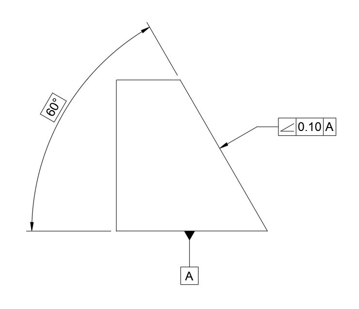
Example drawing
See Angularity on a drawing
Tolerance zone visualized
See the tolerance zone in context
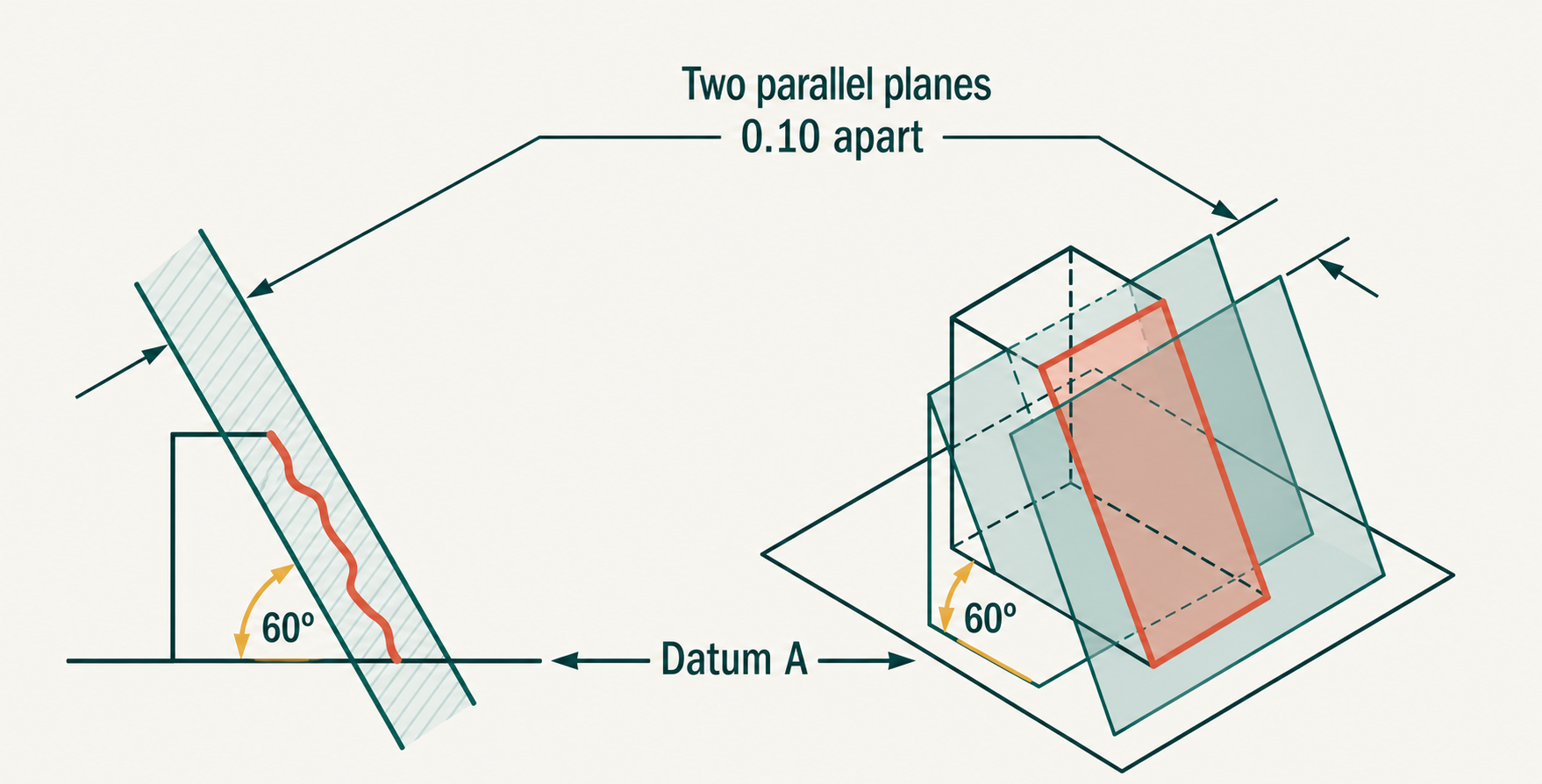
The angle itself is exact; variation lives in the zone
Angularity needs a basic angle to define its target orientation. The boxed 60° (for example) is theoretically exact. The feature may vary only by staying within the tolerance zone positioned at that angle relative to its datum.
Example feature control frame
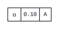
The angled face must lie between two parallel planes 0.10 mm apart, oriented at the basic 60° angle to datum A.
Practical use
When to use Angularity
Choose angularity for a functional slope or axis that is neither parallel nor perpendicular to its datum: a valve seat, tapered locating surface, or angled bore are typical examples.
Inspection
How it is usually measured
Create the datum setup first. A CMM, sine fixture with indicator, or an angular measuring setup can then evaluate the surface or axis against the basic angle. Measuring only the printed angle with a protractor misses the geometric zone and its datum relationship.
Common mix-up
The angle shown on the drawing must be basic (theoretically exact), usually enclosed in a box.
Keep exploring
 Straightness
 Flatness
 Circularity
 Cylindricity
 Profile of a Line
 Profile of a Surface
 Perpendicularity
 Parallelism
 Position
 Circular Runout
 Total Runout
 Concentricity
 Symmetry