What it controls
Perpendicularity is the GD&T control for “square.” It keeps a surface or axis at 90° to a datum within a stated zone. A surface, center plane, or feature axis.
The tolerance zone
How the zone works
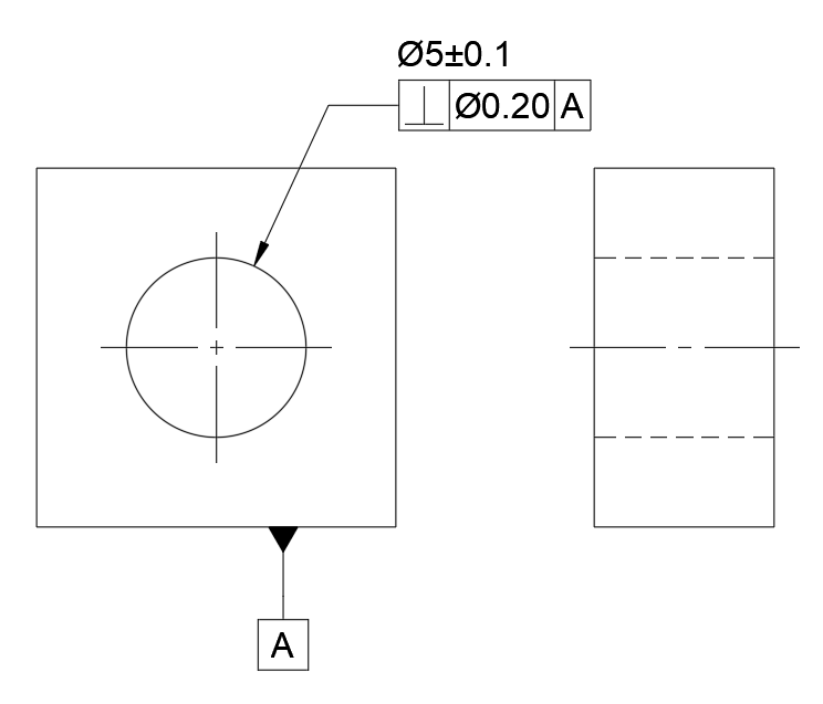
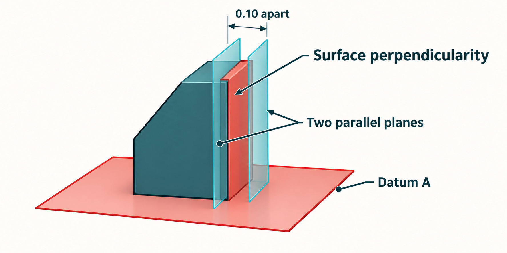
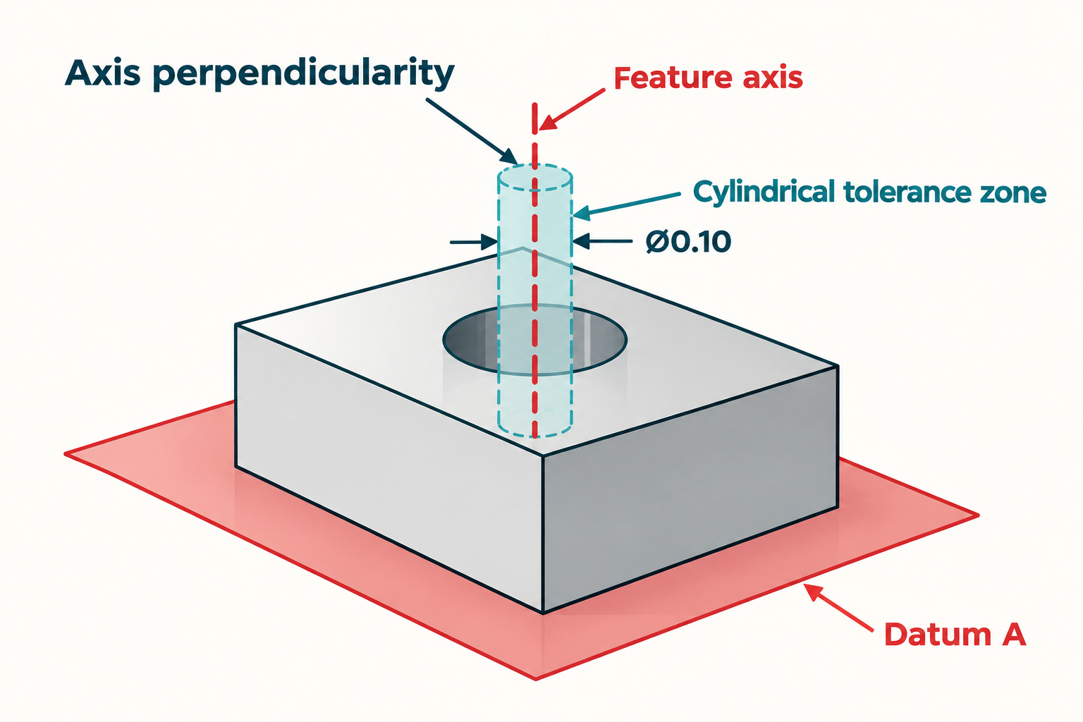
A surface must fit between two planes held at exactly 90° to the datum. A hole or pin axis usually must remain within a cylindrical zone whose axis is perpendicular to the datum plane.
Example drawings
See Perpendicularity on a drawing
Tolerance zone visualized
See the tolerance zone in context
“Square” depends on the datum
Perpendicularity is not a general visual impression of squareness. It is a relationship between the controlled surface, center plane, or axis and the datum feature identified in the frame. Change the datum, and you change the inspection setup and possibly the result.
Example feature control frame
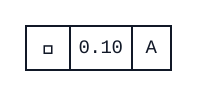
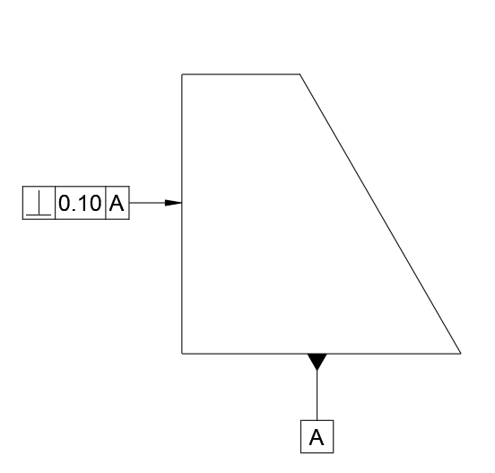
The controlled surface must stay within a 0.10 mm tolerance zone perpendicular to datum A.
Practical use
When to use Perpendicularity
Use it for a face that must stand square to a mounting face, or for a bore/pin axis that must enter a mating component without leaning.
Inspection
How it is usually measured
Simulate or establish the datum first. A surface can be checked with a height gage, square, indicator, or CMM; an axis normally needs a CMM or functional gage. For axis controls, verify that the diameter symbol and the datum setup match the intended cylindrical zone.
Common mix-up
For an axis, the diameter symbol is typically required because the tolerance zone is cylindrical.
Keep exploring
 Straightness
 Flatness
 Circularity
 Cylindricity
 Profile of a Line
 Profile of a Surface
 Angularity
 Parallelism
 Position
 Circular Runout
 Total Runout
 Concentricity
 Symmetry