
What it controls
Parallelism limits how much a feature can tilt away from a datum. A surface must fit between parallel planes; an axis is commonly controlled within a cylindrical zone. A surface or a feature axis.
The tolerance zone
How the zone works
For a surface, two planes separated by the tolerance are held parallel to the datum. For an axis, a cylindrical zone is commonly oriented parallel to the datum axis. The zone controls tilt, not distance from the datum.
Example drawing
See Parallelism on a drawing
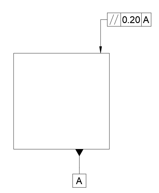
Tolerance zone visualized
See the tolerance zone in context
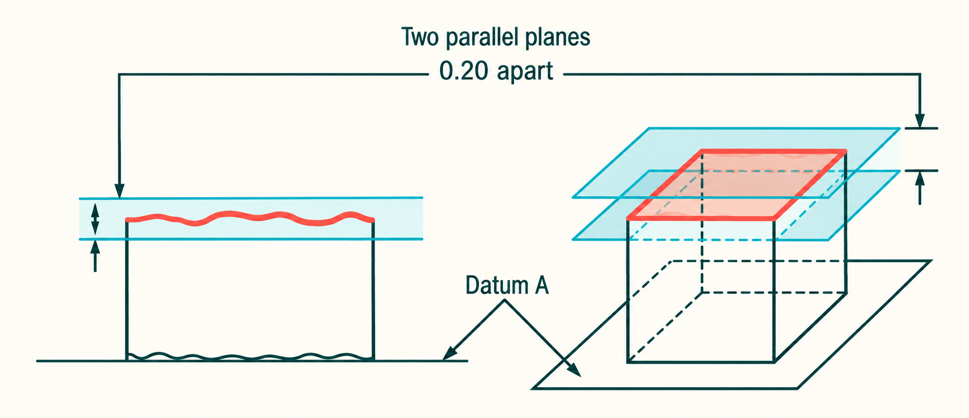
Orientation only—not height or spacing
A surface can be perfectly parallel to datum A and still be at the wrong height. The size or location dimension carries that distance requirement. Parallelism simply keeps the controlled feature from leaning away from the datum reference.
Example feature control frame
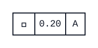
The indicated surface must remain between two planes 0.20 mm apart that are parallel to datum A.
Practical use
When to use Parallelism
Use it for guide faces, ways, opposing surfaces, or axes that need to run in the same direction as a functional datum but do not need a tighter location control.
Inspection
How it is usually measured
Establish the datum feature, then sweep the controlled surface or derive the controlled axis relative to it. A height gage on a surface plate, indicator setup, CMM, or functional fixture can work when the setup truly simulates the datum. Do not confuse a raw difference in readings with parallelism until the datum reference is established.
Common mix-up
Parallelism controls orientation only. It does not establish the distance from the datum.
Keep exploring
 Straightness
 Flatness
 Circularity
 Cylindricity
 Profile of a Line
 Profile of a Surface
 Angularity
 Perpendicularity
 Position
 Circular Runout
 Total Runout
 Concentricity
 Symmetry